


How do, we as mill builders, size a drive train to your needs? Well, depending on the roll forming or tube mill markets, we strive for different results. If you are speaking about roll forming machines, we generally size the drive train for the maximum product (strip width and wall thickness) at the maximum line speed (generally 100 FPM). We will size the total mill horsepower so the maximum product size will utilize 100% load from the motor at the motor’s base speed. Base speed for a motor (AC or DC) is defined when the motor reaches maximum horsepower and maximum torque at the same time. Below is a chart depicting this scenario (assuming a 100 HP motor, 1150 revolutions per minute or RPM base speed as an example).

Figure 1
As you can see, for the roll forming markets, this is predominantly the best method and most common practice. Technically, the roll forming machines can go faster, whereby the motor is taken past base speed (commonly known as “overspeeding”). An interesting thing happens once this action is performed (as the chart shows). The horsepower stays constant while the torque begins to drop off. Thus, if the roll former needed to go faster, it could do so but only on the lighter gauge products. Typically, this is not necessary because there are many other limiting factors on the roll forming system that will limit speed.
This scenario is not so easy with the tube mill systems. Various products, various yield strengths of materials, and various speeds all play into the drive train design and motor efficiency utilization. However, the same scenario plays out–you want to gear the mill into the largest horsepower draw, that is typically the largest OD, heaviest wall thickness, and highest yield strength. If you gear the mill so that the horsepower curve meets full potential at the base speed (where you need the most torque) on the largest product, you will be in a favorable position to allow your lighter products to go faster. Consequently, the lighter products will pull less torque that matches the natural drop of the motor once it surpasses the designated base speed.
Most motors are designed around base speeds of 850, 1150, and 1750. The top speeds are normally between 2000 and 2500 RPM. Thus, motors that hit full horsepower at lower RPMs will provide much higher torque than a motor that will hit full horsepower at higher RPMs (see chart below for 100 HP at 850 and 1750 RPMs base speeds).
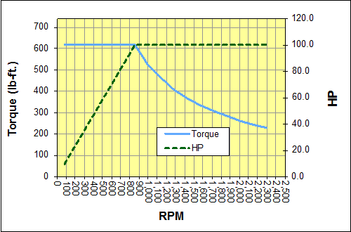
Figure 2

Figure 3
Studying these charts also hints at possibilities of eliminating “shift reducers”. These types of reducers can often make difficult products run easier on older mills.
The difficult task is developing the equations that will correctly model the loads and yield required horsepower and torque. Formtek has developed these equations through years of experience, experimentation, and theoretical calculations. We have the power to handle your application.