


Tooling
It becomes evident that the tooling components, the accuracy of the tooling, the precision with which it is assembled and adjusted, and the rigidity of the assembly are vital to the end result. Because of the importance of the proper tooling, the details that make up proper tooling should be considered in more depth.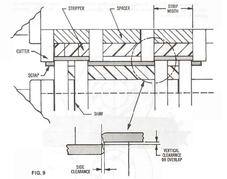
The tooling setup (Fig. 9) is composed of cutters, spacers, strippers and shims. The cutters, spacers and shims are locked up tightly on the arbor between a nut and a shoulder on opposite ends. The arbors must be precise and properly proportioned so as to minimize deflection, and they should rotate in suitable bearings to minimize radial and lateral run out.
The cutters are arranged so that pairs of male and female cuts alternate on the top and bottom arbors. The distance between the female pair establishes the strip width, so side clearance is commonly set by shimming the male cutter. The amount of clearance is determined by the metal characteristics and is theoretically established so the fracture line starting down from the top meets the fracture line starting up from the bottom. The vertical clearance is also a function of metal thickness and hardness, and is set by adjusting one arbor relative to the other. This clearance may be positive, with cutters overlapped as in (Fig. 9), zero, or negative with the cutters separated.
Obviously, cutters cannot be permitted to flex sidewise. They must be thick enough, and supported sufficiently to withstand the compressive forces of deformation and the “roll over” couple that develop. These same forces cause the metal to wedge tightly between the female knives. It is the function of the strippers to force the metal out from between these cutters and at the same time resist the force system trying to impart lateral bow of “dish”.
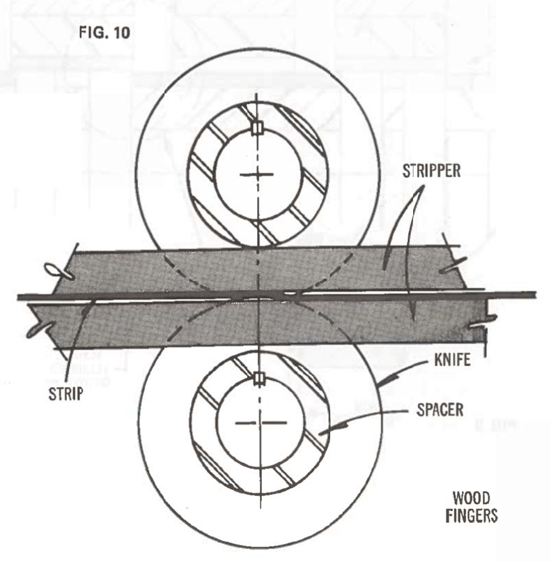
Strippers (Fig. 10) may be strips of wood, either plain of cloth covered, supported on the entry and exit side of the cutters with mechanical adjustments to provide the needed pressure against the strip surface.
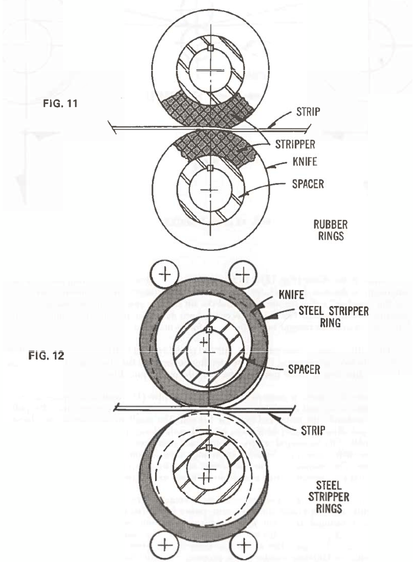
Other common types of strippers are neoprene rinds (Fig. 11) over the cutter spacers with compression of the ring employed to develop stripping pressure; or they may be (Fig. 12) eccentrically mounted steel rings over the cutter spacer. In this case strip ring pressure results from the force of adjustable rollers bearing against the ring circumference. The most common arrangement is use today is the neoprene ring concept. However, excellent results are available with all.
The Complete Line Force System
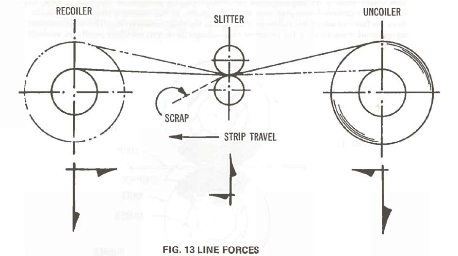
Although the slitter (Fig. 13) is to be considered the heart of the slitting line, it is one component of the complete package. The fundamental arrangement also includes an uncoiler to hold the “Mother” coil, a recoiler to rewind the slit strands, and a scrap disposal system, all operating synchronously. The cutting force had been discussed, but an understanding of the complete concept involves recognition of the other forces in action.
The cutting force is concentrated upstream of the vertical center of the arbors, and may be resolved into two components, (1) a force tending to separate the arbors and (2) a force parallel to the direction of metal travel representing the pull required to cut.
Likewise, the forces of concern at the uncoiler involve (1) vertical component representing the weight of the coil and drum, and (2) a horizontal component representing the pull needed to “unbend” the metal and to rotate the coil. The resultant of these, when related to coil width and allowable shaft deflection, establishes the design proportions of the shaft and drum assembly. The horizontal or power component represents forces developed at the uncoiler, at the slitter, and at the recoiler depending entirely upon the mode of operation of the complete line. The resistance to this component at the uncoiler is represented by the WR2 of the coil and by braking effort commonly designed as part of the uncoiler assembly.
The coil weight and drum weight combine to create a vertical force at the recoiler acting in conjunction with a horizontal or, again, power force. The power force in this case is composed of rotational effort and most significantly, the pull required to create a tightly wound coil and, depending on the mode of operation of the complete line, the pull required to slit and uncoil. Here again the resultant of these forces, when related to coil width and shaft deflection, establishes recoiler design proportions while the horizontal component establishes the power requirements.
Operating Modes
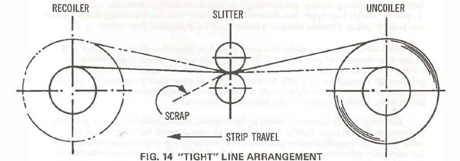
In a broad sense, slitting line arrangements fall into two categories, (1) those operating in a “pull-through” mode and (2) those known as “drive” type. The pull-thought arrangement is by far the more common. It functions on a “tight-line” basis (Fig. 14) with the metal under tension from the uncoiler to the recoiler. All the power of this line is provided by the recoiler motor as pull on the strip to uncoil, rotate the slitter arbors and shear the metal, and, of course, to recoil. Because the strip must rotate the arbor assembly, this mode of operation finds its application limited by the ability of the strip to accommodate the pull required.
Further, the pull required may be limited to the center strands being slit, since the outer strands have a tendency to become loose. (More about this later)
The electrical systems usually supplied permit the strip speed to increase in proportion to the coil diameter buildup on the recoiler. However, systems are available which will hold the strip speed constant regardless of coil diameter. However, systems are available which will hold the strip speed constant regardless of coil diameter. Although it may be drawing a fine line, constant speed will result in improved and more consistent slit edge quality.
The most familiar type of drive slitting line also applies the “tight-line” principle. However, the slitter in this case is powered to rotate the knives, thus propelling the strip at a given rate. A mechanical slip clutch, and electrical slip clutch, or some other speed compensating device is made part of the recoiler drive train so the strip speed holds constant as the coil diameter increases.
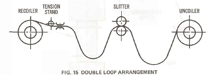
In a “pure” drive slitting line (Fig. 15) the slitter is powered both to rotate the arbors and to shear the metal.
By virtue of a slack loop in the strip ahead of and on the exit side of the slitter, each function – uncoiling, slitting, and recoiling – is, in a sense, independent. This arrangement is called a “double loop-type” line. Reactionary or “back” tension for coiling in this type of line is developed in a tension block or a tension roll stand ahead of the recoiler.
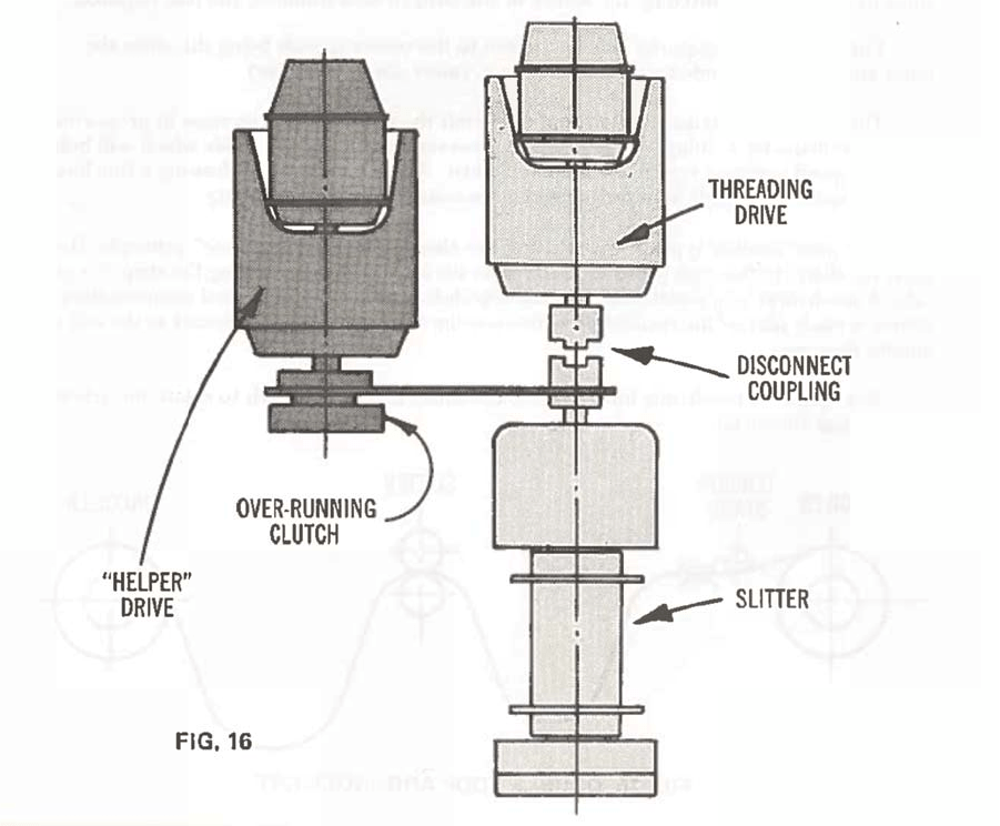
Drive slitting lines are applied to a great many low strength, soft alloys, and in any other instance, where the strip is likely to tear in a pull-through type machine. As a compromise, manufacturers today offer what is known as a “helper” or “booster” type pull-through arrangement (Fig. 16). It extends a general duty slitter’s capability to include light gages and low yield strength metals at much less than added cost involved for a driven slitter installation to cover the full range considered.
The slitter in this instance is driven by two motors, one an induction motor geared-in and sized to feed all gages, light as well as heavy, at some normal threading speed. The other is a torque regulated motor geared-in to rotate the cutters at maximum strip speed, but sized only with enough to overcome the friction and inertia in the slitter arbor assembly.
When operating conventionally, after threading, bother motors are inoperative and pull on the strip from the recoiler provided all the work – to rotate the cutter assembly and to shear. In the “helper” mode, after threading, the torque regulated motor is operative and accordingly, relieves the strip from the need to rotate the arbors.