


Since the inception of longitudinal tube welding process, there has always been a need to remove the weld bead on the outside of the tube so that the tube has a nice “round shape” that carries over the weld joint. In some cases, you may need a nice flat profile if you are welding a shape that is formed into a shape directly (and not later reshaped into the profile). The act of removing this welding upset presents many problems to both the process and operator. If not removed, then the weld bead upset is essentially pushed back into the parent material which then may cause weld bead issues (strength, longevity, smoothness, etc.) The specific act of removing the weld bead is typically based on welding method used to create the weld bead in the first place. That is, an HF induction weld bead is not processed the same way as a laser weld bead. Therefore, the solutions to remove said weld bead can normally be characterized by their parent welding methods. Two predominant welding methods exist when discussing longitudinally welded profiles:
Bead Removal Methods for Forge Welding
For the most common method of tube production, forge welding, the typical method of removing the weld bead is by scarfing. The style most common is what is called a dual tandem trimmer (as shown in figure 1).

Figure 1: Dual Tandem Trimmer
This style unit has been around for over 50 years and has two (2) carbide cutting tools (typically square shaped with four cutting edges). The idea is that while one head is cutting the red-hot welding bead, the other head can be prepared so that it will be ready to drop and begin cutting once the first head becomes dull. Two things make this difficult to perform in reality:
- The bead is red hot and razor sharp so the operator must be extremely careful.
- The locations of the two heads are slightly different in the moving tube direction. This causes an extra second so the weld bead may not react the same since it is cooling rapidly. Thus, some operators like to use the first head only and keep the second head as back up.
There is another type of weld bead removal method that also utilizes the scarfing action but instead of a square carbide bit, this unit uses a half round carbide bit (as shown in Figure 2).
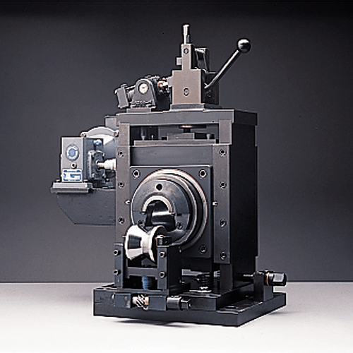
Figure 2: Roto-scarf. Photo Courtesy of Addison Machine Tool.
With this type of unit, the carbide tools last much longer as they have a much “longer” cutting edge. The downside is that the carbides also cost much more. In some applications, such as high-speed production, the longer cutting edge means you can run a longer amount of time before having to change a tool bit which may cause line stoppages.
Bead Disposal Methods for Forge Welding
With either scarfing method, the bead being removed is often red-hot and razor sharp. Handling of this bead is the true area of difficulty. Traditional methods of bead handling focus around the winding of the scarf (as shown in figure 3).
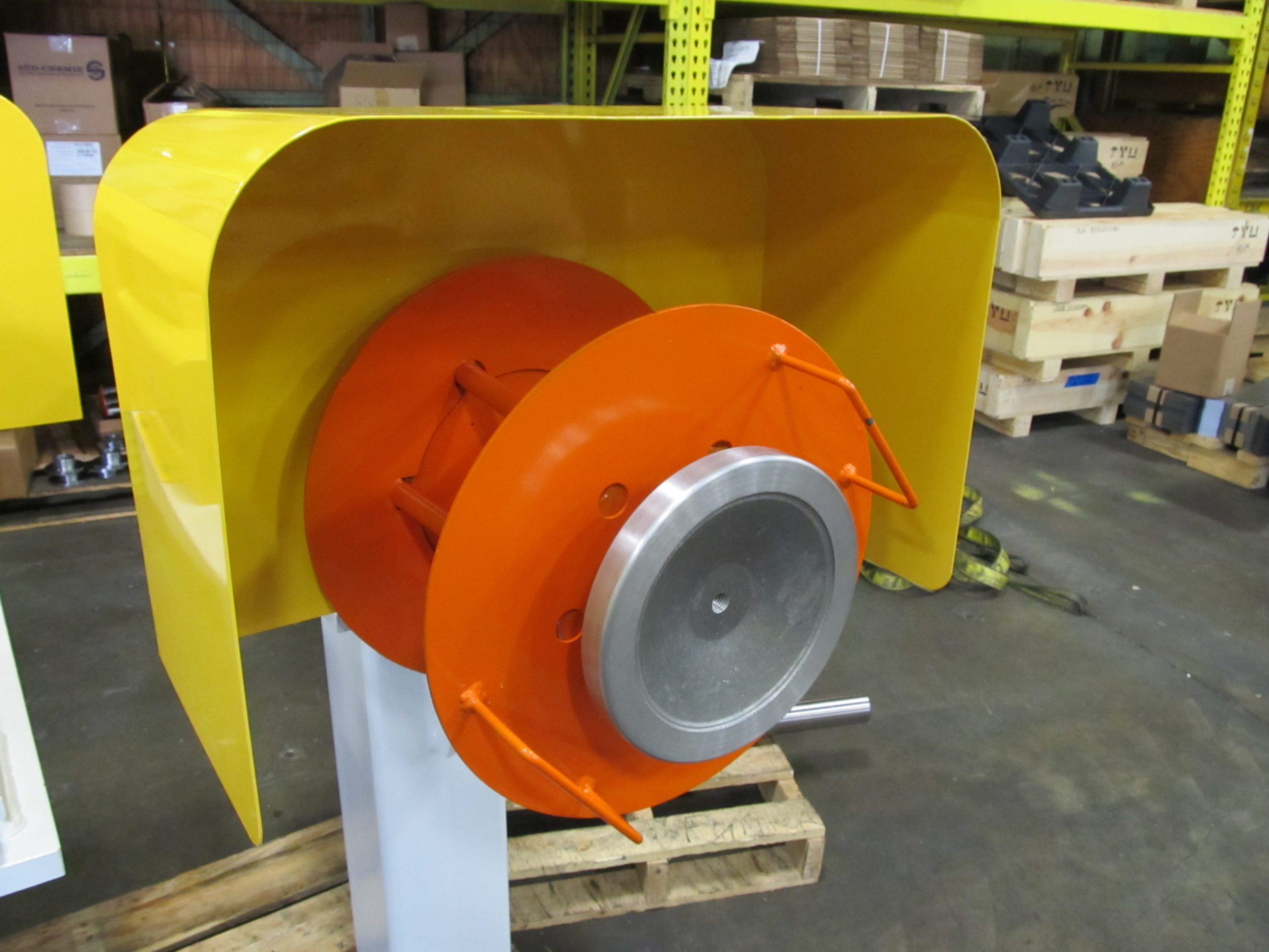
Figure 3: Bead Winder. Photo Courtesy of Formtek – Yoder
As you may well imagine, the operator has to be very careful and wear protective sleeves in order to not get hurt. In addition to this, if the line is a high-speed line then the speed of rotation for such a device is quite fast, again increasing risk to operators.
Many years and many ideas later, the mills basically continue to practice this operation. Ideas of choppers resting above the tandem trimmer, compactors and knickers have come and gone with limited success. The idea of chopping the scarf into smaller pieces had promise and the market continued to work on this idea and refine the design.
Why does the chopping idea hang around? First, you make the area much safer for the operator by eliminating the need to manage windings. Second, you have smaller pieces to send to the scrap collectors and they pay a higher premium for those smaller pieces vs. large windings. The evolution of scrap chopping has yielded some very special products and the key to success really stems to how close you can place the chopping head to the actual scarfing device. This improves the success rate and lessens possible jamming effects. Of course, you have to ensure the bead is fairly uniform in cross-section. A well-maintained roll toolset, accurate setups, and consistent strip widths will normally result in uniform bead cross-sections.

Figure 4 HF 3-roll Weld Squeeze Box with Single Tandem Bead Trimmer and Integrated Chopper (left). Photo Courtesy of Formtek – Yoder and Similcut.

Figure 5 Close up of Single Tandem Bead Trimmer and Integrated Chopper (left). Photo Courtesy of Formtek – Yoder and Similcut
Since we are chopping up the bead in small lengths (2” or 50 mm for example), the individual pieces need to transported away from the scarfing area. Typically, this is done via a magnetic scrap conveyor.

Figure 6 HF Welding Area with Scrap Conveyor. Photo Courtesy of Formtek – Yoder
Bead Removal Methods for Fusion Welding
The fusion welding bead removal methods are drastically different. Due to processing speed differences, fusion welding is often a factor of 10 to 20 times SLOWER than HF welding. Slower speeds make it more difficult to remove the bead with a scarfing operation due to the fact that the tool starts to chatter while engaging. As you can imagine, carbide inserts due to perform well when chattering vibrations start. This new variable requires a slightly different approach.
The most common OD bead control methods used in fusion welding typical revolve around grinding the weld. However, some people believe that you can control the weld bead characteristics using specialized devices that can swirl the “TIG arc” to smooth out the weld bead. This can be done but it does slow the entire line down slightly. It is a tradeoff that must be determined favorably by the management.
There are two basic types of bead grinding:
- Belt Wheel
- Flapper Wheel
Belt grinding uses a sanding belt to reduce or remove the fusion weld bead. Due to speed differences between TIG and laser welding, one or two units may be required. Bead grinding normally requires coolant to help increase the life of the belts. Grinding fines are also carried away with the coolant as well.

Figure 7 OD Bead Grinding by Belt. Photo Courtesy of Formtek-Yoder and Bossi, srl.
The flapper wheel design normally runs dry and there are several variations and uses a flapper paper-based wheel. Since the flapper wheels cannot remove as much material as a belt, several units are often used inline.
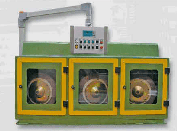
Figure 8 Flapper Wheel Bead Grinder (Multi-head). Photo Courtesy of Olimpia 80.
Depending on the selection, the OD bead grinding unit must be sized for the bead size and speed of the process to ensure a round presentation.
Since laser welding speeds are improving, experimentation has been done with scarfing laser weld beads but with limited success. Who knows what may be possible in the future? There have been talks of actual “machining” of the weld bead and this may become a reality in the next iteration of the weld bead conditioning. The only guarantee is that these processes are moving wherever efficiency and safety are taking them.