


It’s an established fact that the consumption of coiled steel or coiled metals is rapidly increasing. The continuity it provides, the opportunity for scrap reduction, the material and production economies and the improved product consistency are all advantageous to more production fabricating processes. Side trimming and multiple slitting of coils may be performed at the mill during processing, or by the fabricator, to obtain size accuracy, to create a desired edge quality, or to meet a particular product demand, and thus is a very significant process.
Slitting can be applied to either non-ferrous or ferrous metals, some non-metals like fiber and paper, and with variety of rolled or applied finishes. Moreover, it can be applies to a variety of gauges and widths encompassing material as thin as foil and as thick as plate. Be
tween these two extremities lies a flat rolled product classification know as “Sheet Coil and Strip”. It is to the slitting of this classification the bulk of this paper is directed.
Product Quality and Control
It is Fundamental that rotary slitting is performed by passing material between between circular knives mounted on a par of parallel arbors. It is logical, then, and also fundamental to ask various questions, such as:
- What defines edge and strand quality?
- What quality factors are to be considered?
- How are these factors controlled?

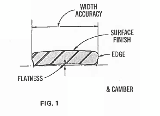
Disregarding chemistry, temper and thickness,over which the slitter has no control, the quality of the slit strand is defined (Fig. 1) by the following characteristics:
- Width Accuracy
- Edge Characteristics
- Flatness
- Camber
- Surface Finish
The factors controlling quality include such details as:
- Equipment Arrangement, Rigidity and Precision
- Tooling Set-Up
- Tooling and machine Maintenance
Line Operating Characteristics- Acceleration
- Deceleration
- Speed Adjustment/Speed Control
- Tension Control
Taking a closer look, a slit edge is developed by thefollowing actions: (Fig. 2)
- Edge Distortion of Roll Over
- Burnishing a Flat of Land
- Fracturing of the Material
- Burr Formation

All of which develop progressively along the line of travel, over the interval of x –x, as illustrated in (Fig.3). The overlap of cutters is exaggerated in the diagram.
The action is similar to that of the progression of shearing with a raked blade. Magnifications taken in increments along this line depict the development of the slit edge, as described and illustrated below.
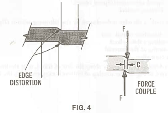
First, the edge distortion, or “roll-over” (Fig. 4) which develops during initial penetration, is caused by the plastic flow of metal under a compressive load and also from the force couple created by the cutting pressure and side clearance between cutters.
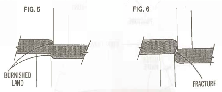
The burnished land (Fig. 5) is formed in the next stage of penetration. Here the metal deforms plastically along the side of the cutter. The result is a shiny and relatively flat surface.

Further penetration (Fig. 6) exceeds the ultimate strength of the material in the shear with fracture resulting. The angle of fracture and its appearance is related to metal characteristics and cutting clearance.
Burr, (Fig. 7) the final characteristic is caused by (1) a comprehensive displacement around whatever radius exists on the edge of the cutter and (2) a tensile separation at the fracture line, leaving what is the best described as “string ends”.

Strand width must be measured across the burnish land and it would seem that width accuracy would be governed completely by the accuracy of the distance between a pair of cutters. There is, however, another very important consideration. The force couple, (Fig. 8) already mentioned, plus the compressive forces developed during penetration, applied at both edges, act in opposite directions. If not restricted, they impart lateral bow of “dish” in the strand affecting its flatness and likewise its width. Equally as important to these forces are any irregularities or inequities in this system of forces resulting from non-uniform clearances or from a dull cutter acting to impart edgewise bow or camber in the slit strand.

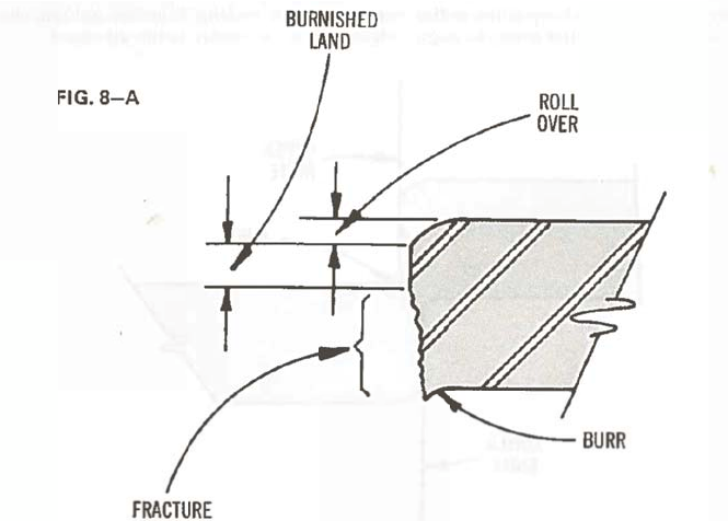
Figure (8A) illustrates the characteristics of a good slit edge. The edge has minimum “roll-over”, a well-defined burnished land, a clean fracture, and minimum burr.
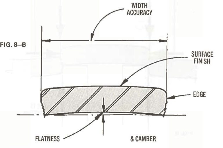
Figure (8B) shows the characteristics that define a quality strand. That is, a quality strand. That is, a quality strand has good slit edges, minimum “dish”, minimum chamber, width accuracy, and a surface quality that has not been marred during slitting.
This post is part of the series, “Rotary Slitting Principles and Applications.” Stay tuned for more details on machinery, applications, and methods related to slitting. To see machines related to sheet metal slitting, click here.
I found your article interesting thank you – we’ve had similar issues when developing our roll cut down machine (slitter rewinder alternative technology) and managed to solve runability issues by integrating a single large blade to make a single pass cut in one stroke to the roll core. This has produced a really nice end result and is much faster than the older, traditional slitter rewinder machines. Primarily used for paper, towel, and nonwovens which we have designed a special blade for as well. It’s fascinating once you get into how things work and how these processes operate to be able to see how to improve them.