Yoder Square Wave ERW Welder
The goal of the Yoder Square Wave ERW Welder is to combine all the good things from both conventional AC welding and DC welding. This means a welder that’s as easy to maintain as an AC welder but delivers the performance of a DC welder.

| Brand | |
|---|---|
| Solution | |
| Industry | |
| Application |
Product Details
Resources
Questions?
Product Details
Questions?
Resources
Life Before the Square Wave Welder
For a full appreciation of the square wave welder, it is necessary to review the history of ERW starting in the early 1920’s. Prior to that time, welded steel tubing was made by heating the edge areas of a formed tube by one means or another and subsequently forcing the edges together to create a forged weld.
The advent of the modern electrical resistance welder began with Johnston, who was granted a patent in the early twenties for a system which simultaneously applied heat and pressure to the tube. His method involved keeping the seam open prior to the welding throat which included a pair of copper electrodes to provide the welding current.
AC Welding
In Johnston’s preferred version, the weld was produced by a sinusoidal AC welder. The output voltage and output current for an AC welder are illustrated in Figure 1.
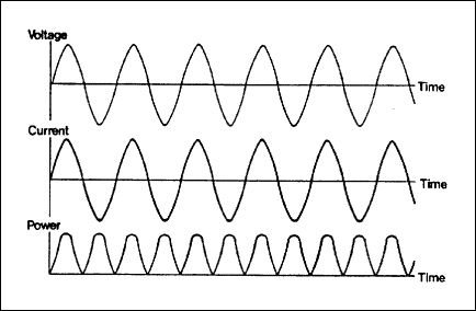
By taking the instantaneous product of the output voltage and output current, the output power can be plotted. The bottom curve seen in Figure 1 shows the power “peaks” that result from an AC power supply. During the time when the power decrease towards and increases from zero, there is very little heat output. As this happens, the weld is colder. These cold areas are commonly referred to as “stitches”.
To compensate for these cold periods, the maximum output power (i.e., the peaks) must be raised over what is actually necessary for a good weld. This excess heat is transferred by conduction to the stitches to obtain a constant weld. (refer to Figure 2)
During the power peaks, the material is in a molten condition and ferrite balls may be expelled to the inside of the tube due to the magnetic field set up in the tube (commonly referred to as “weld spatter”). The spacing between the peaks of high temperature is a function of the operating frequency of the welder and the line speed of the mill.
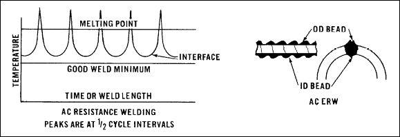
As a rule of thumb is that the line speed should not exceed 1½ times the operating frequency of the welder. For example, a 60-cycle welder should not be operating faster than 90 FPM (60 x 1½ = 90). Should the line speed exceed 1½ times the operating frequency of the welder, there is a risk that 100% grain growth will not be obtained every half cycle and a weld failure may occur (sometimes referred to as a “zipper weld”). Properly matching the operating frequency, line speed of the mill and power setting, would maintain a 100% weld. A change in strip characteristics may require an adjustment in one or more of the preceding variables.
DC Welding
DC welding was first used in an attempt to avoid Johnston’s patent; however, it is obvious that a DC power supply with a constant power output would create a superior weld seam when compared to AC. Unfortunately, this increased weld quality came at a price.
A simple DC welder schematic is shown in Figure 3. The main characteristic of a DC welder is that AC line current is immediately transformed into low voltage/high current. This low voltage/high current then goes through a full-wave rectifier which converts the AC to DC. The DC power unit must be located as close as possible to the weld point to minimize power loss.
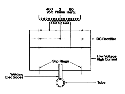
In addition, the low voltage/high current DC is then transmitted through large slip rings to the rotating unit on the tube mill and the welding current is transmitted to the tube through rotating copper electrodes.
The Square Wave Welder
The goal of the Square Wave Welder was to combine all the good things from both conventional AC welding and DC welding. This meant a welder that was as easy to maintain as an AC welder but delivered the performance of a DC welder.
Square Wave Welding Theory
A simple square wave welder electrical schematic is shown in Figure 4. The main characteristic of a square wave welder is that only high voltage/low current is used until you reach the weld point. Electrically, the main difference between the DC and the square wave is that line current is rectified (through a full wave rectifier) without going through a step-down transformer. This is a high voltage/low current rectifier, and this high voltage/low current is then fed through a DC chopper and inverter which chops the DC into a special square wave AC.
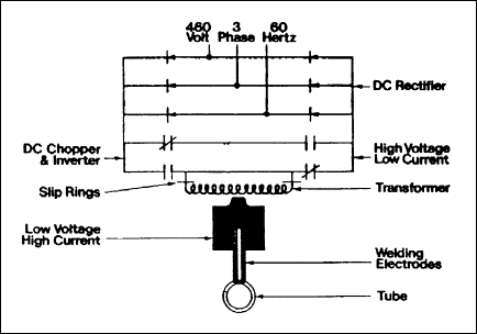
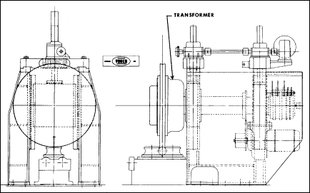
This high voltage/low current is then transmitted through conventional slip rings to the rotating unit on the tube mill and the high voltage/low current is transformed into low voltage/high current in a “vapor-cooled”, single output transformer. The power is then transmitted to the tube through the rotating copper electrodes. The entire assembly is shown in Figure 5.
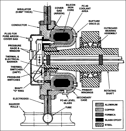
A cross-section of a vapor-cooled welding transformer is shown in Figure 6. Although the term “vapor-cooled” is a coined term, it refers to the use of FC-40 freon coolant medium inside the transformer to take heat away from the transformer components. The absorption of heat causes the coolant to vaporize, hence the term vapor-cooled, and rise to the copper casing of the transformer. Here, it condenses thereby releasing its heat to the externally cooled casing.
Square wave power units may be located wherever it is convenient to the plant layout. The square wave welder produces a square wave of power – not merely a square wave of voltage.
Square Wave Output Power
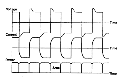
Figure 7 shows the power curve for a square wave welder. Voltage and current form a square wave and, even though they are changing direction approximately 200 times per second, they are in-phase and traveling in the same direction so the resulting power area is achieved. The little dip between cycles represents the amount of time (approximately 0.15 milliseconds) that it takes to go through zero which is further illustrated by Figure 8 which shows voltage across the electrodes.
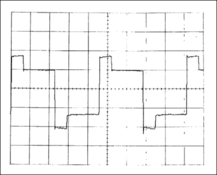
The angle of the lines going from plus to minus represents the switching time. The slight blip at the top and bottom of each half cycle represents a slight overshoot due to forced voltage introduced when passing through zero. This cuts down considerably on the amount of time it takes to change direction and keeps the area of power constant.
For all practical purposes, both the DC and square wave deliver constant power output.
How is power transmitted to the tube?
With the AC welder, current is traveling back and forth across the vertex at the operational frequency; with DC it is traveling across in one direction only and with square wave it is traveling back and forth at 400 times per second. With AC and square wave, there is a frequency effect which helps concentrate the current on the strip edges, and allows a variety of forming techniques to be used. DC requires special forming.
Tube diameter has no significant electrical affect on AC, DC or square wave efficiency. Wall thickness is generally the main factor determining speed versus power available; however, tube diameters from approximately 3/8″ to 5/8″ may present some speed restriction (mostly on thicker strip) due to a possible limitation transmitting full power from the electrodes to the tube. Mechanical forming variations, end use requirements, strip characteristics, etc. may also be a consideration. Sizes as small as 3/8″ diameter can be run successfully on AC, DC and square wave welders.
What does the Tube see in the way of heat?
DC & Square Wave Welding
Since both the DC and square wave welders have a constant power rating, there is no compensation for periods of low power necessary. Consequently, the power can be set so that the temperature is maintained between the melting point and minimum good weld lines. Figure 9 shows this arrangement with a typical cross section of the weld shown at the right hand side. Typical of the DC and Square Wave welds are a uniform O.D. and I.D. weld bead upset, no periodic stitch and absence of ferrite balls or weld spatter inside of the tube.

What about HF welding?
The main disadvantage to AC, DC and square wave welding is that it is a contact process that requires good electrical conductivity to achieve a weld. These welders are applicable only to low-to-medium carbon (0.05 to 0.20 carbon equivalents and 0.21 to 0.33 carbon equivalents with reduced speed and special procedures) clean surfaced steel. This can be either cold rolled or hot rolled pickled and oiled.
Consequently, HF induction welders employ a non-contact method of power transfer. This means they can weld any type of “weldable” material, which includes many grades of carbon or special alloy steels (cleaned or un-cleaned); many of the nonferrous such as aluminum, copper alloys, stainless steels; and many of the exotic materials.
What are characteristics of the different welds?
AC, DC & Square Wave Welds
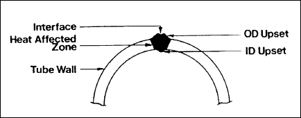
Figure 10 shows a typical cross section of an AC, DC or square wave weld which typically is trapezoidal in shape with more of the weld bead upset to the outside than the inside. It is approximately 2/3 to the outside and 1/3 to the inside, but variations in the way the strip edges come together can vary the amount of bead extruded both inside and outside. The typical AC, DC or square wave weld has a wide heat-affected zone.
HF Welds
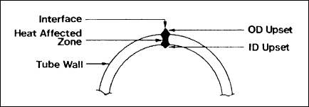
Figure 11 shows a typical cross section of an HF weld which is characterized by an hourglass shape and a very narrow heat-affected zone.
Welder Comparisons
There is no doubt that in today’s world, the square wave welder is a niche welder. Consequently, HF induction welding is by far the preferred method of welding on most mills.
Square Wave vs. AC and DC Welders
The major advantages of the square wave welder when compared to the other two conventional ERW methods (i.e., AC and DC welding) are listed in Table 1 below.
| Criteria | AC | DC | Square |
| Susceptible to Weld Spatter | Yes | No | No |
| Susceptible to Weld Stitching | Yes | No | No |
| Location of Power Supply Important | No | Yes | No |
| High Maintenance Cost | No | Yes | No |
Square Wave vs. HF Welders
The advantages of the square wave welder when compared to the HF welder are listed as follows:
More Forgiving Weld Presentation
With HF welding, the presentation of the weld seam is critical to the success of the process. Although important with square wave welding, it is not nearly as critical. In addition, because the electrode wheel is contoured to the radius of the tube being welded, it can be used to hold the form of the open tube during welding. This feature is especially useful on smaller tubes where it is difficult to control the edges.
No Impeder Required
Because square wave welders (as well as AC and DC) do not require the use of any inside impeder, the I.D. of the tube is free of any mechanical devices. This is especially important when welding tubes with very small diameters, where it is physically difficult to put enough ferrite inside the tube to efficiently and effectively HF weld. One typical application is the production of carbon-steel refrigeration or fuel line grade tubing.
Another application where the lack of an impeder is preferred is when some sort of inline I.D. coating of the tube is being performed. The presence of an impeder would make it difficult to deliver the coating substance to the inside of the tube.
Higher Welding Heat Transfer Efficiency
Because square wave welding is a contact welding process, the heat transfer efficiency of the process is much greater than HF induction welding. Although HF contact welding is also a contact method, it is generally not used on the smaller tube sizes and, therefore, does not typically compete with square wave welding.
Wider Heat Affected Zone
In situations where severe bending of the weld zone is required, a square wave welded tube may have some benefits over comparable HF induction welded tubes. With the advent of hydro-formed tubular products (i.e., tube sections that are deformed using hydraulic pressure to expand them inside a dieset), there is some speculation that the wider heat-affected zone on a square wave welded tube may be more plastic. Although further data was not available at the time this paper was written, experiments designed to support this theory will be conducted shortly.
“Retrofittable” to Existing Systems
Because the square wave power supply is essentially an AC power supply, it can used to replace aging AC power supplies. By doing so, tube manufacturers can increase the weld quality and, by doing so, increase the production yield on the mills.
In addition, the second generation of square wave power supply incorporates a solid state design that allows finer control of the output wave form. This added control allows the welder to be tuned to the specific tube being produced on the mill. The result is again better weld quality and increased production yields. Furthermore, the newer power supplies offer high reliability and increased availability of spare parts and service.
Conclusion
Although the Square Wave Welder may not be the best welder for every application, it does fill a niche in today’s market. In addition, the possibilities of its use in the hydro-form tube industry make it a viable welder for today’s tube producers.
Resources
Related Products from Other Formtek Brands
Get a Quote
Need help with a Budget Estimate to determine overall equipment costs to determine if your project can be justified? Looking for a Firm or Detailed Quote for your equipment needs? Please reach out — we'd be happy to help.


