


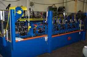
Yoder Cold-Stretch Reduction Small Diameter W-10 / W-15 Tube Mill
In response to the increasing world wide demand for small diameter (i.e., 0.188″ to 0.375″ OD) steel tube for both refrigeration and automotive purposes, Yoder can provide equipment for production of these tubes. Since 1992, complete Yoder Cold-Stretch Reduction Small Diameter W-10 / W-15 Tube Mill Systems have been supplied to Turkey, China (2 lines), South Africa, and the United States. This U.S. line may be the first new mill of its type installed domestically in the last fifteen years.
Product Details
Resources
Questions?
Product Details
Questions?
Resources
A typical line begins with a double swivel uncoiler, a coil end joiner and a strip accumulator. This arrangement allows the tube mill to run continuously without stopping to change coils of steel.
The coil end welder is typically a portable design that moves in-line for welding and out of line when not in use. An air shear gives a distortion free cut allowing for the strip ends to fit up perfectly at the weld station. The weld is automatic with the TIG weld process at a 15° bias. The TIG weld requires no grinding and adds no build up at the weld area.
After the coil end joiner, the material enters the strip accumulator. For accumulating strip, three (3) basic designs are typically used – the overhead accumulator or “looper”, the vertical spiral accumulator or “Floop”, and the horizontal spiral accumulator. The following table addresses the pros and cons of each design:
| Type | Advantages | Disadvantages |
|---|---|---|
| Overhead | – Least expensive – Simple design – Easy to maintain |
– Uses overhead space – Storage limited to length of unit |
| Vertical Spiral | – Adequate storage – Small footprint |
– Most complicated design – Difficult to maintain |
| Horizontal Spiral | – Adequate storage – Small footprint – Less expensive than Vertical Spiral |
– Requires more floor space than Vertical Spiral |
From the strip accumulator, the strip is cleaned before entering the forming and welding mill. Cleaning can be done using either fiber or wire brushes and steam or possibly with an ultrasonic cleaner. The addition of a mild solvent may also be useful. The intent is to re-move all mill oils and foreign particles from the strip to insure that the eventual ID of the tube will be as clean as possible.
Once clean, the strip enters for the forming and welding mill. Here the strip passes through a series of contoured horizontal and vertical rolls that form it into a tube. The driven mill stands incorporate integral rolls and roll shafts along with precision bearings to minimize any out-of-roundness or “runout” in the shafts and tooling to produce the highest quality tube possible. Furthermore, the forming mill is run without the use of roll coolant to pre-vent the contamination of the ID of the tube being formed.
As the strip edges close to form a ½” OD mother tube, a welder is used to join them. There are three common types of welder used on mills of this type (commonly referred to as “refrigeration tube mills”). They are: DC contact welding,AC Square Wave contact welding, and high-frequency induction welding. Yoder’s recent experience is with the last two methods.
High-frequency (H.F.) induction welding’s main advantage is that it is a non-contact welding process. Unlike Square Wave or DC welding, the weld power is induced through a weld coil rather than mechanically delivered through contacts to the tube. However, H.F. induction welding does have some drawbacks.
 The main disadvantage of the H.F. induction welder is that it requires the use of a cooled, ferrite impeder inside the tube at the welding point. On standard tube mills, this normally does not represent a problem because the impeder can be cooled simply by flushing water through the impeder sleeve and into the inside of the tube. However, because of the critical inside cleanliness requirement of this mill’s tubing, the impeder must be cooled without allowing water to come in contact with the ID of the tube using one of two methods. In the first method, the coolant must be returned back out of the impeder along the same line that it entered using what is called a “return flow” impeder. This is difficult to do because of the physical size of the tube being welded and the restricted cooling capacity of the water.
The other method reverts to a conventional “flow through” impeder with liquid nitrogen as the coolant rather than water. The method has additional benefit though. As the nitrogen warms, it becomes a gas which in turn provides the required protective gas atmosphere for the ID of the tube. This atmosphere protects the tube from corrosion and is usually supplied by an inert gas generator when not using liquid nitrogen.
The other type of welder used by Yoder is its own exclusive Solid State AC Square Wave welding system. This system consists of a power supply that feeds high voltage, low current through a DC chopper and inverter which chops the DC into a special square wave AC. This high voltage, low current is then transmitted through conventional slip rings to a rotating toroidal transformer and a pair of electrodes. The electrodes then deliver the weld power to the weld joint on the tube.
The advantages of the Square Wave system are that it does not require the use of an impeder, the electrodes can be used to assist in controlling the weld seam presentation, and lower weld temperature used in this process reduces the risk of ID weld spatter. The disadvantage is that it is a contact process; therefore, the electrodes are a wear item that require “dressing” or trimming typically once a day.
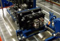
After the tube is welded, the OD weld upset bead is removed using a scarfing tool, the tube is cooled by water sprays, and it enters the reducing mill. The reducing mill incorporates twenty (20) passes of tooling (ten (10) driven horizontal and ten (10) idle vertical) to progressively squeeze the tube down to its final diameter. All of the driven and idle stands are mounted on removable sub-plates or rafts. These rafts allow for quick changeover from one size to the next.
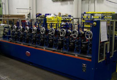
The use of individual digital AC drives on each of the driven passes allows the equipment to compensate for the increasing tube speed caused by the tube elongation during the reducing process. From the ½” OD mother tube, the reducing mill is capable of producing a 0.188″ OD minimum tube. Output speeds can exceed 600 FPM when making the smallest tube.
After the last reducing pass, the tube is generally passed through a non-destructive, Eddy current tester. This unit is designed to look for small pin holes in the weld seam. If found, the unit can track the defect through the remaining processes to the end of the line where it can be marked and cut out as scrap.
Because the reduction process occurs at room temperature, the tube is work hardened and, in most cases, needs to be annealed. To anneal the tube inline, an induction annealing section is typically used to heat the tube to a maximum temperature of 1450ºF. Once heated, the tube is then air cooled using a protective gas atmosphere in an after cooling line. Be-cause of the high mill speed, the cooling section can be several hundred feet in length. Once cooled to below 800ºF, the tube is then quenched in a water bath.
Depending on the end product, the tube can now be coated. Coatings can range from a simple copper electroplate (i.e., refrigeration tube) to a complex zinc or Galfan (a licensed zinc-based material) coating followed by a paint coating (i.e., automotive fuel line tube). Regardless of the process, they can all be done in-line.
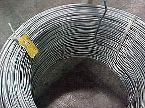
The final stage is to have the tube either cut for straight lengths or wound into coil form. For straight lengths, the tube is passed through a small two-plane straightener and into a shear type press. Once cut, the tube is dumped to a storage bin by a tube runout table. If the tube is to be coiled, it continues past the runout table and into a tube coiler.
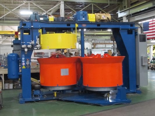
The tube coiler incorporates an oscillating bending roll to continuously vary the coil diameter as the tube is being run. The coiler’s three-basket design allows the operator to unload a finished coil while a new coil is being wound. Depending on the customer’s preference, the defective tubing found by the Eddy current tester can be either paint marked or knurled by a unit located on the incoming side of the coiler. The coiler can also be set to cut out the marked product and/or index to a new basket.
It is important to note that refrigeration tube mills are unlike other types of tube mills. Although the basic tube making concepts are similar, refrigeration tube mills must be viewed more as a process than simply a line of equipment. Furthermore, the added complexity of the various processes (e.g., cleaning, annealing, coating, coiling, etc.) make them more difficult to understand and learn, but with good equipment design and well thought out process design, the line can become much more manageable.
Resources
Related Products from Other Formtek Brands


Get a Quote
Need help with a Budget Estimate to determine overall equipment costs to determine if your project can be justified? Looking for a Firm or Detailed Quote for your equipment needs? Please reach out — we'd be happy to help.